How to Fix ABS Brakes
What are ABS Brakes?
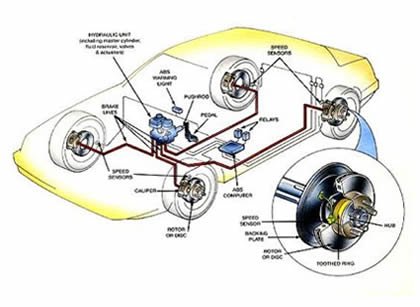
The Four-Wheel Anti-lock Brake System (ABS) is an electronically operated, all wheel brake control system. Major components include the power brake booster, master cylinder, the wheel speed sensors, and the
- Disc Brakes
- Brake Rotors
- Brake Caliper
- Vacuum Booster
- Drum Brakes
- Wheel Cylinders
- ABS
- Master Cylinder
If equipped the traction control system controls wheel spin by modulating engine torque and applying then releasing the appropriate rear brake to restore traction when driving on slippery or loose surfaces.
ABS Components
The anti-lock brake system consists of the following components:
- Vacuum booster and master cylinder assembly
- Hydraulic Control Unit (HCU) and control module assembly
- Wheel speed sensors
- Brake Pedal Position (BPP) switch
ABS Speed Sensors
ABS Sensor Removal & Installation
Front
To Remove:
- Before servicing the vehicle refer to the precautions in the beginning of this section.
- Raise and support the vehicle.
- Remove or disconnect the following:
- Front anti-lock brake sensor electrical connector
- Routing clips
- Bolt
- Front anti-lock brake sensor
To Install:
- Install or connect the following:
- Front anti-lock brake sensor. Tighten the bolt to 9 ft-lbs (12 Nm)
- Routing clips
- Front anti-lock brake sensor electrical connector
- Lower the vehicle.
Rear
To Remove:
- Before servicing the vehicle refer to the precautions in the beginning of this section.
- Raise and support the vehicle.
- Remove or disconnect the following:
- Rear anti-lock brake sensor electrical connector
- Routing clips
- Bolt
- Rear anti-lock brake sensor
To Install:
- Install or connect the following:
- Rear anti-lock brake sensor. Tighten the bolt to 80 in-lbs (9 Nm)
- Routing clips
- Rear anti-lock brake sensor electrical connector
- Lower the vehicle.
ABS Module/Hydraulic Control Unit
Removal & Installation
To Remove:
- Before servicing the vehicle refer to the precautions in the beginning of this section
- Remove or disconnect the following:
- Battery ground cable
- Battery tray
- Electrical connectors and wiring
- Brake lines
- ABS/HCU assembly mounting bolts and ABS/HCU assembly
- Mounting screws and anti-lock brake control module
- Nuts and mounting bracket
To Install:
- Install or connect the following:
- Mounting bracket to ABS control module. Tighten screws to 80 in-lbs (9 Nm)
- Anti-lock brake control module electrical connectors
- Mounting screws and anti-lock brake control module. Tighten screws to 27 in-lbs (3 Nm)
- ABS/HCU assembly mounting bolts and ABS/HCU assembly. Tighten screws to 15 ft-lbs (20 Nm)
- Brake lines. Tighten to 13 ft-lbs (17 Nm)
- Electrical connectors and wiring
- Brake lines
- Battery tray
- Battery ground cable
Bleeding The ABS System
Bleeding
WARNING
Use of any brake fluid other than approved DOT 3 or DOT 4 will cause permanent damage to brake components and will render the brakes inoperative.
WARNING
Brake fluid contains polyglycol ethers and polyglycols. Avoid contact with eyes. Wash hands thoroughly after handling. If brake fluid contacts eyes flush eyes with running water for 15 minutes. Get medical attention if irritation persists. If taken internally drink water and induce vomiting. Get medical attention immediately.
CAUTION
Do not allow the brake master cylinder reservoir to run dry during the bleeding operation. Keep the brake master cylinder reservoir filled with the specified brake fluid. Never reuse brake fluid that has been drained from the hydraulic system.
CAUTION
Brake fluid is harmful to painted and plastic surfaces. If brake fluid is spilled onto a painted or plastic surface, wash it with water immediately.
NOTE: When Air can get into the brake system and cause a spongy brake pedal when any part of the hydraulic system has been disconnected for repair or installation of new components. This requires bleeding of the hydraulic system after it has been correctly connected. The hydraulic system can be bled manually or with pressure bleeding equipment.
Manual Bleeding
- Connect the scan tool DLC cable adapter into the vehicle data link connector. (DLC) under the dash and follow the scan tool instructions.
- Clean all dirt from around the master cylinder cap.
- Remove the brake master cylinder filler cap and fill the brake master cylinder. reservoir with the specified brake fluid.
- Bleed the brake system in the order displayed on the scan tool. Place a box end wrench on the bleeder screw. Attach a rubber drain tube to the bleeder screw and submerge the free end of the tube in a container partially filled with clean brake fluid.
- Have an assistant hold firm pressure on the brake pedal.
- Loosen the bleeder screw until a stream of brake fluid comes out. While the assistant maintains pressure on the brake pedal tighten the bleeder screw.
- Repeat until clear, bubble-free fluid exits the bleeder screw.
- Refill the brake master cylinder reservoir as necessary.
- Tighten the bleeder screw.
- Repeat Steps 4, 5, 6, and 7 for the remaining bleeder screws in the system.
Pressure Bleeding
- Clean all dirt from around the master cylinder cap.
- Remove the brake master cylinder filler cap and fill the brake master cylinder reservoir with the specified brake fluid.
- Master cylinder pressure bleeder adapter tools are available from various manufacturers of pressure bleeding equipment. Follow the instructions of the manufacturer when installing the adapter. Install the bleeder adapter to the brake master cylinder reservoir and attach the bleeder tank hose to the fitting on the adapter.
- Bleed the longest line first. Ensure that the bleeder tank contains enough specified brake fluid to complete the bleeding operation. Place a box end wrench on the RH rear bleeder screw. Attach a rubber drain tube to the RH rear bleeder screw and submerge the free end of the tube in a container partially filled with clean brake fluid.
- Open the valve on the bleeder tank.
- Loosen the RH rear bleeder screw. Leave open until clear, bubble-free brake fluid flows then tighten the RH rear bleeder screw and remove the rubber hose.
- Continue bleeding the rear of the system. Move in order from the LH rear bleeder screw to the RH front disc brake caliper bleeder screw ending with the LH front disc brake caliper bleeder screw.
- Close the bleeder tank valve. Remove the tank hose from the adapter, and remove the adapter.