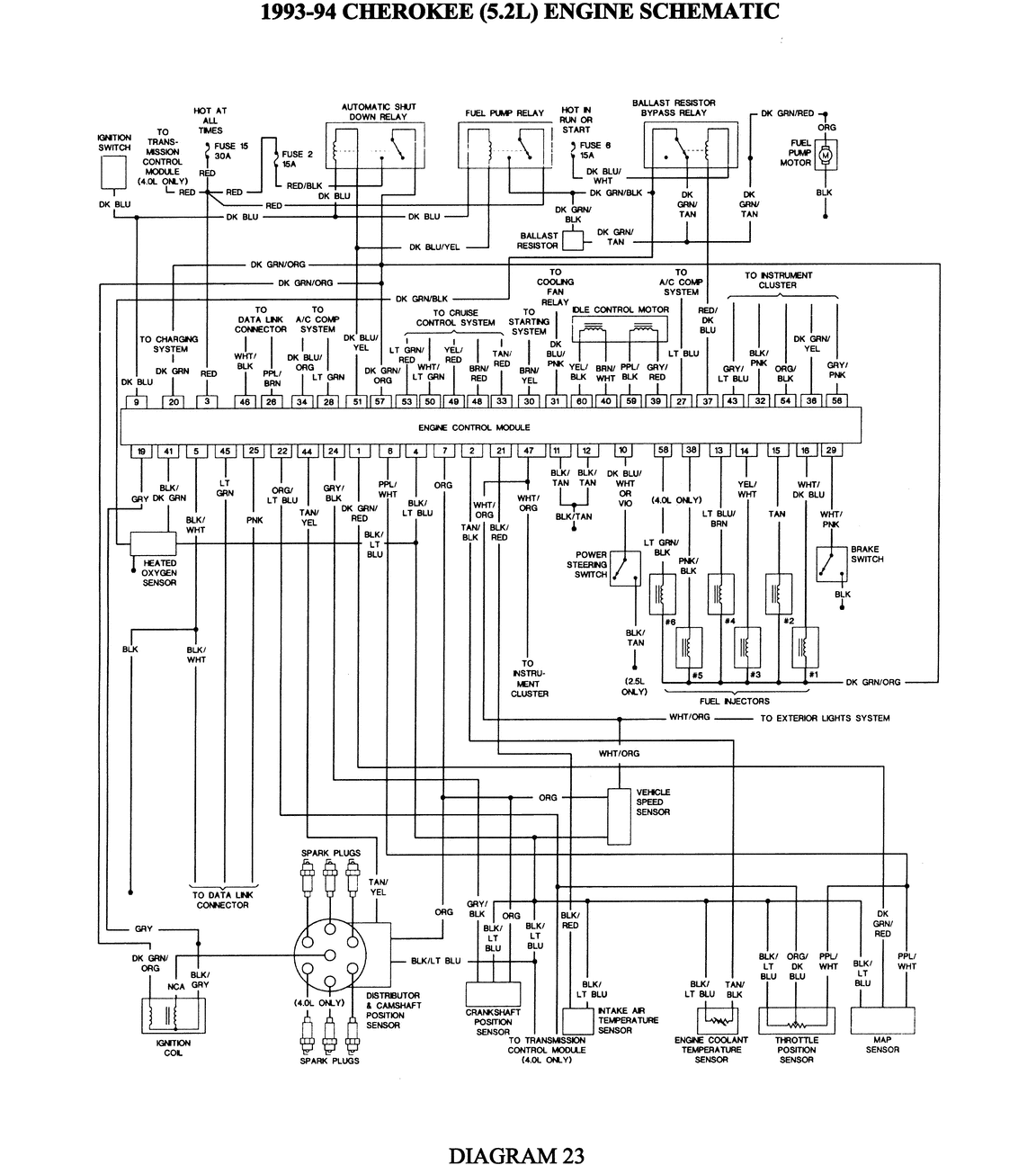
My Jeep has been running fine, and when I parked it in front of the house this afternoon, I went to start it later and it would crank, but not start. I checked for spark…there was none, what so ever. After the engine cooled down completely, it started right back up. I was told to check the crank position sensor, but not only do I not know where it is, I am unsure how to test it when I do find it. Please help! It’s my only way to get to and from work everyday. Thank you! It has a brand new fuel filter and fuel pump as well.
Looking at the diagram you might want to rule out a stiking auto shutdown relay first.
Crankshaft Position Sensor Testing
Unplug the sensor connector from the ignition control module and connect an ohmmeter between terminals A and B as marked on the connector. The ohmmeter should read 125–275 ohms on a hot engine. Replace the sensor if the readings are not as stated.
Crankshaft Position Sensor Replacement
- The CKP sensor is bolted to the top of the cylinder block near the rear of the right cylinder head. Disengage the sensor wiring connector and remove the two sensor mounting bolts.
- Carefully pull the sensor out of the cylinder block.
- Installation is the reverse of removal.
Camshaft Position Sensor Operation
The camshaft position sensor, or CMP sensor is located inside the distributor. The ECU uses the CMP signal to determine the position of the No. 1 cylinder piston during its power stroke. ECU uses this information in conjunction with the crankshaft position sensor to determine spark timing among other things.
The CMP sensor contains a Hall effect device which sends either a 0.0 volt or a 5.0 volt signal to the ECU depending on the position of the distributor shaft.
If the cam signal is lost while the engine is running, the ECU will calculate spark timing based on the last CMP signal and the engine will continue to run. However, the engine will not run after it is shut off.
Camshaft Position Sensor Testing
- Insert the positive (+) lead of a voltmeter into the blue wire at the distributor connector and the negative (−) lead into the gray/white wire at the distributor connector.
NOTE: Do not unplug the distributor connector from the distributor. Insert the voltmeter leads into the back side of the connector to make contact with the terminals. - Set the voltmeter on the 15 volt AC scale and turn the ignition switch ON. The voltmeter should read approximately 5 volts. If there is no voltage, check the voltmeter leads for a good connection.
- If there is still no voltage, remove the ECU and check for voltage at pin C-16 and ground with the harness connected. If there is still no voltage present, perform a vehicle test using tester M.S.1700, or equivalent.
- If voltage is present, check for continuity between the blue wire at the distributor connector and pin C-16 at the ECU. If there is no continuity, repair the wire harness as necessary.
- Check for continuity between the gray/white wire at the distributor connector and pin C-5 at the ECU. If there is no continuity, repair the wire harness as necessary.
- Check for continuity between the black wire at the distributor connector and ground. If there is no continuity, repair the wire harness as necessary.
- Crank the engine while observing the voltmeter; the needle should fluctuate back and forth while the engine is cranking. This verifies that the stator in the distributor is operating properly. If there is no sync pulse, stator replacement is necessary.
