Having troubles with the heating/AC/entire climate control in my car. No power is going to the buttons, they don’t light up and nothing is working. Because it seems like no power is going to the buttons, it then does not heat or cool and no fans turn on, nothing. Wondering if it disconnected somewhere, but I don’t know where to look.
First thing to check would be the fuses. This is where the power comes from.
Next you could check the connections on the back of the switch/controls for power and connection. Then check the wiring to see where the power loss is located in case a wire is cut or damaged if no power is found.
2010 Honda Civic HVAC Controls Wiring Diagram 1

2010 Honda Civic Instrument Panel Wiring Diagram

Automatic Temperature Control System DESCRIPTION
SYSTEM OPERATION
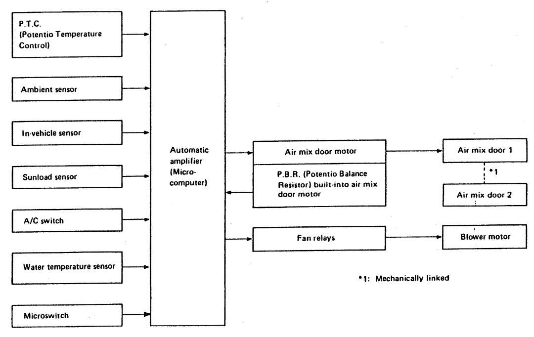
The automatic temperature control regulates air temperature, air mix door control and blower speed to maintain operator “set temperature.” This is determined by ambient temperature, in-vehicle temperature, amount of sunload, set temperature and A/C switch signals. The air outlet door, intake door and compressor magnet clutch are controlled by the manual operation of each switch.
When the engine coolant temperature is low, the air outlet door position is detected by the microswitch, if this is set in B/L, FOOT or FOOT/DEF blower speed is controlled to prevent cold air from being discharged into the floor area.
The intake door control is selected by changing the REC switch position. The outlet door control is selected by changing the mode switch. When the A/C switch is ON, the thermistor detects evaporator temperature. The thermo control amplifier controls compressor magnet clutch control operation depending on evaporator temperature.
SYSTEM COMPONENTS
Refer to Fig. 1 for system component input and output controls and switch sensor usage combinations.
Fig.1
Air Mix Door Motor
The air mix door motor rotates so that the air mix door is opened to a position set by the auto amplifier. Motor rotation is sent through a shaft. The air mix door position is fed back to the auto amplifier by P.B.R. built into the air mix door motor.
Ambient Temperature Sensor
This sensor transforms ambient temperature into a resistance value which is input to the automatic amplifier.
Automatic Amplifier
This amplifier has a built in microcomputer enabling it to accept data and provide precise system control which is necessary for driving the automatic air conditioner mode. This microcomputer has a self-diagnosis mode program.
Automatic Amp. Relay
When the A/C and fan switch are ON, the auto amp. relay operates and transmits A/C operation signals to the auto amplifier.
In-Vehicle Sensor
These sensors convert the temperature value of inside air which is drawn through the aspirator fan, into a resistance value which is input to the automatic amplifier. The head level sensor detects upper half body level temperature and the foot level sensor detects foot level temperature.
Microswitch
The microswitch is at the side link of the heater unit and operates the link in response to the position of the mode switch.
Potentiometer Temperature Control (P.T.C.)
The P.T.C. is used to set desired in-vehicle temperature.
Fan Control Amplifier
The amplifier controls main radiator fan speed (HI or LO) according to base current transmitted from the automatic amplifier when the compressor operates.
Sunload Sensor
This sensor is located in the right defroster grille assembly. It transforms sunlight into a current value, which is then input to the auto amplifier.
Water Temperature Sensor
This sensor converts water temperature value at heater core entrance into resistance value, then inputs voltage that varies according to resistance value change into the auto amp.