I was in an accident which broke my passenger side control arm. I bought another one and have been attempting to replace the old one but I can’t seem to get all the parts to connect. If I connect to the rotor first then the middle one is problematic because I can’t put torque on the bolt enough to make it get straightened out. If I connect to the middle one first I can’t seem to connect to the rotor without there being about an inch distance. I’ve attempted to loosen from the strut which allows me to connect those but then I can’t connect back to the strut because it’s off by an inch. Any suggestions are welcome. Thanks
Body shop may be needed to straighten out whatever is bent from the accident. May not be what you wanna hear but short of getting out some torches and bending or realigning it I think you are best to leave it to the pro’s on this one.
Control Arm Replacement Labor Time

Front Lower Control Arm Replacement
Suspension fasteners are critical components that affect performance of vital components and systems. Failure of these fasteners may result in major service expense. Use same or equivalent components if replacement is required. Do not use a replacement component of lesser quality or substitute design. Tighten fasteners as specified.
REMOVAL
- Remove wheels and tire.
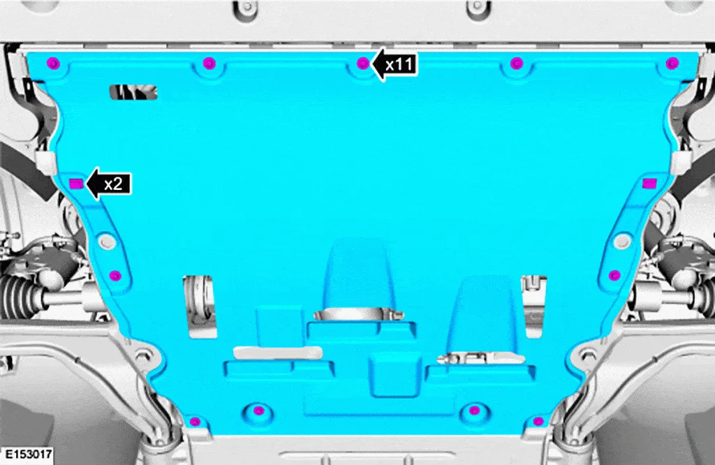
- Next Remove retainers and under body shield, Fig. 2.
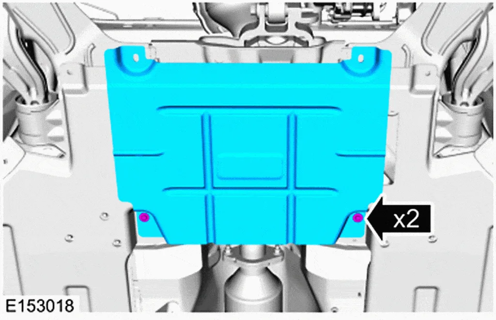
- Remove retainers and center under body shield, if equipped, Fig. 3.
- Remove retainers and floor pan under body shields, lefthand if equipped, righthand as required, Fig. 4.
- Then Remove and discard ball joint pinch bolt and nut and separate ball joint from wheel knuckle, Fig. 5.Do not use a prying device or separator fork between ball joint and wheel knuckle. Damage to ball joint or ball joint seal may result. Only use pry bar by inserting it into lower arm body opening. Use care when releasing lower arm and wheel knuckle into resting position or damage to ball joint seal may occur.
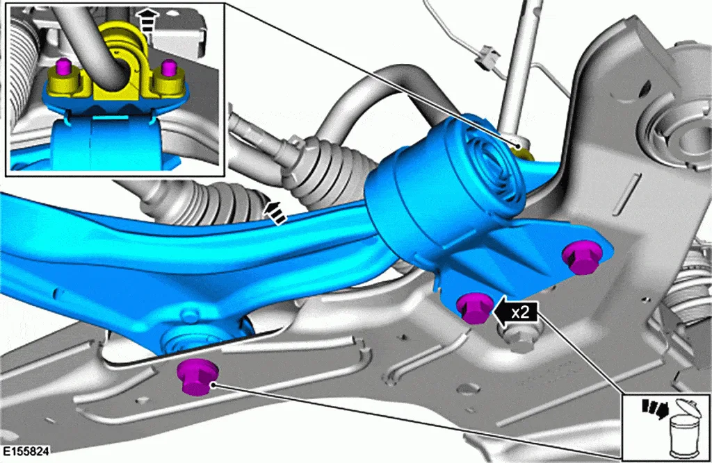
- Remove and discard lower arm forward and rearward bolts and remove lower arm, Fig. 6.
INSTALLATION
Tighten suspension bushing fasteners with suspension loaded or with weight of vehicle resting on wheels and tires, otherwise incorrect clamp load and bushing damage may occur.
- Install new lower arm rearward bolts (1) and tighten finger tight, Fig. 7.
- Install new lower arm forward bolt (2) and tighten finger tight, Fig. 7.
- Raise suspension to curb height using suitable vehicle/axle stands.
- Torque new lower arm rearward bolts (1) to 122 ft. lbs., Fig. 7.
- Torque new lower arm forward bolt (2) to 159 ft. lbs., Fig. 7.
- Position ball joint into wheel knuckle and install new ball joint pinch bolt and nut, Fig. 8.Torque nut to 76 ft. lbs.
- Install floor pan under body shields and retainers, as required, Fig. 4.
- Install center under body shield and retainers, if equipped, Fig. 3.
- Then Install under body shield and retainers, Fig. 2.
- Install wheels and tires.
- Inspect and adjust front toe, as required, as outlined in “Toe Adjust.”


