I have a rod knock and I’m not sure how to access bearings. From the top or bottom? I’m a single mom and I can’t afford a shop so I gotta do this myself. Any tips would be great
Purchase an online manual subscription for your specific make and model. It should provide all the removal and installation procedures along with torque specs. Buy Auto Repair Manual
CONNECTING ROD R&R
REMOVAL
Caution: After the installer hub bottoms on the support assembly, do not exceed 5,000 psi pressure, this could cause damage to the tool.
This procedure is to be used for oversized pistons only. Standard size pistons are supplied as an assembly consisting of a piston, piston pin, connecting rod and piston rings.
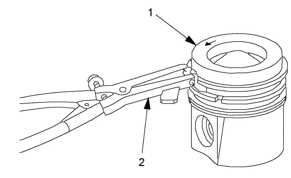
- Using piston ring pliers, remove the piston rings from the piston, Fig. 1.
- Install fork insert tool No. J-24086-310, or equivalent into fixture tool No. J-24086-10, or equivalent, which are part of piston pin remover/installer base set tool No. J-24086-C, or equivalent, Fig. 2.
- Install the piston and connecting rod assembly onto fixture tool No. J-24086-10, or equivalent, Fig. 3.
- Install the J-24086-107 onto the piston pin and J-24086-88A through the fixture and onto J-24086-107, which are part of piston pin remover/installer base set tool No. J-24086-C, or equivalent, Fig. 4.
- Press the piston pin from the piston and connecting rod assembly, Fig. 4.
- The piston and pin are a matched set and are not to be serviced separately. Mark, sort organize the piston and the matching piston pin.

Piston ring removal and installation tool set


INSTALLATION
Caution: After installer hub bottoms on the support assembly, do not exceed 5,000 psi pressure, this could cause damage to the tool.
Caution: Use a piston ring expander to install the piston rings. The rings may be damaged if expanded more than required.
This procedure is to be used for oversized pistons only. Standard size pistons are supplied as an assembly consisting of a piston, piston pin, connecting rod and piston rings. Assemble the piston for the specific cylinder with the connecting rod for the corresponding crankshaft journal.
Ensure that the marks on the piston and connecting rod are aligned the same as when removed. If installing a new piston, ensure that the arrow on top faces towards the front of the engine. If no identification marks were made during disassembly, ensure that the flat area on the bottom of the piston pin skirt is aligned with the small dimple above the connecting rod crankshaft bearing bore.
To provide an effective compression seal, the ring gaps must be staggered a minimum of 90°.
- Install fork insert tool No. J-24086-310, or equivalent into piston and connecting rod assembly onto fixture tool No. J-24086-10, or equivalent, which are part of piston pin remover/installer base set tool No. J-24086-C, or equivalent, Fig. 2.
- Lubricate the piston pin with clean engine oil.
- Assemble the piston, connecting rod and adapter J-24086-6A and install onto fixture J-24086-10, which are part of piston pin remover/installer base set tool No. J-24086-C, or equivalent, Fig. 5.
- Adjust installation pin J-24086-9 to G-4, Fig. 6.
- Insert pin tool No. J-24086-9, or equivalent through fixture tool No. J-24086-10, or equivalent, which are part of J-24086-C set and to the piston pin, Fig. 7.
- Press pin tool No. J-24086-9, or equivalent until it bottoms on fixture tool No. J-24086-10, or equivalent, Fig. 7.
- Using piston ring pliers, install the piston rings onto the piston, noting following:
a. Install the oil control ring spacer into the bottom groove of the piston.
b. Install the lower oil control ring. The oil control rings do not have a dimple or orientation mark and may be installed in either direction.
c. Install the upper oil control ring.
d. Install the middle compression ring with the dot facing up.
e. Install the top compression ring in either direction. The ring has no orientation markings.
MAIN & ROD BEARING R&R
CONNECTING ROD
- Lightly lubricate piston, rings, cylinder bore and bearing surfaces with suitable, clean engine oil.
- Piston alignment mark must face front of engine block.
- Install piston and connecting rod into proper cylinder bore using connecting rod guide tool No. J-41556, or equivalent.
- Lightly tap piston top until all rings enter cylinder bore using suitable wooden hammer handle.
- Install bearing, cap and bolts.
- Torque connecting rod bearing cap bolts to 15 ft. lbs.
- Final tighten cap bolts an additional 75 degrees.
- Ensure connecting rod side clearance is .007-.017 inch.
MAIN BEARING
- Dip crankshaft bearing cap bolts in suitable, clean engine oil.
- Upper and lower inserts may be different. Do not obstruct any oil passages.
- Place crankshaft bearing inserts into crankshaft bearing cap and block.
- Ensure bearing inserts project an equal distance on both sides.
- Ensure insert tangs are engaged.
- Lubricate crankshaft main bearing surface with suitable, clean engine oil.
- Install crankshaft.
- Apply a .12 in bead of suitable sealant crankshaft main bearing cap No. 4 sealing surface.
- Tap crankshaft bearing caps into block cavity using suitable brass, lead or a leather mallet before installing bolts. Do not use bolts to pull crankshaft bearing caps into seats.
- Install crankshaft main bearing caps.
- Apply small amount of suitable sealer to rear of crankshaft main bearing cap No. 4 sealing surface.
- Torque crankshaft main bearing cap bolts to 37 ft. lbs.
- Final tighten cap bolts an additional 77 degrees.
- Ensure crankshaft end play clearance is .002-.008 inch.
