Home » Car Questions » Replace Valve Spring and Seals 2010 Enclave Buick

Replace Valve Spring and Seals 2010 Enclave Buick

You gave me the labor time to replace the valve spring on my Enclave and I was shocked to see it was only 7.9 hours. My question is can you tell me what special tools are needed? Also do you know what all is required to be removed to do this I have already pulled the intake and valve cover but I thought it would need the timing chain removed so the cam can be pulled to do the spring but I cant imagine all that is done in just 7.9 hours so I am trying to figure out how this is done?


To be clear the Labor time to remove and replace the valve springs is 7.9 hours for the right bank only. It is 12.3 for both banks.

For full instructions that include images and diagrams Select your vehicle specific Auto Repair Manual Here.

2010 Buick Enclave R&R Valve Spring Labor Time

Model YearSkill CodeFactory TimeLABOR Time
VALVE SPRINGS, R&R
 Acadia, Acadia Limited,
  All Cyls,
   Right Bank ………………………2009-17B7.9
   Left Bank ……………………….2009-17B8.3
   Both Banks ………………………2009-17B12.3
 Enclave, Traverse,
  All Cyls,
   Right Bank ………………………2009-17B7.9
   Left Bank ……………………….2009-17B8.3
   Both Banks ………………………2009-17B12.3
NOTES FOR: VALVE SPRINGS, R&R
Includes: R&I Valve Cover & Spark Plugs.

Valve Spring Replacement – Right Side

Special Tools
  • EN 46106 Flywheel Holding Tool
  • EN 46110 On-Vehicle Valve Spring Compressor
  • EN 46116 Valve Stem Seal Remover/Installer
  • J 39313 Spark Plug Port Adapter
Removal Procedure
  1. Remove the starter motor.
  2. 2010-buick-enclave-starter-removal-diagram

    NOTE

    Important

    If the EN 46106 flywheel holding tool is not installed, the crankshaft may rotate. If the crankshaft rotates, disassembly and reassembly of the entire camshaft timing system may be required.

    Install the EN 46106 flywheel holding tool in order to prevent crankshaft rotation.

  3. Remove the camshafts and rocker arms.

    Camshaft, Replace

    1.Remove camshaft cover as outlined under “Valve Cover, Replace.”
    2.Remove mounting bolts and position power steering fluid reservoir aside. Do not disconnect power steering pipes or drain power steering fluid.
    3.Disconnect connectors, then remove mounting bolts and Camshaft Position (CMP) sensor.
    4.Disconnect connector, then remove mounting bolts and CMP actuator solenoid.
    5.Remove crankshaft balancer as outlined under “Crankshaft Damper, Replace.”
    6.Rotate crankshaft until camshafts are in neutral, low tension position using crankshaft rotation socket tool No. EN 46111, or equivalent. Camshaft flats will be parallel with camshaft cover rail.
    7.Hold camshafts in place with suitable open end wrench, and loosen camshaft position actuator bolt.
    8.Install timing chain retention tool No. 46108, or equivalent, over lefthand secondary timing chain.
    9.Mark timing chain and actuators for installation alignment.
    10.Remove actuator mounting bolt.
    11.Remove camshaft locking tool from lefthand camshafts, and position lobes in neutral position.
    12.Maintain bearing caps in order for installation in original position.
    13.Remove mounting bolts, bearing caps and camshafts.
    14.Reverse procedure to install, note following:
    a.Ensure crankshaft is in stage one timing drive assembly position.
    b.Ensure camshaft sealing rings are in place in camshaft grooves.
    c.No. 4 identification ring for lefthand intake camshaft is machined off (1); No. 5 identification ring for lefthand exhaust camshaft is machined off (2).
    d.Apply liberal amount of suitable to camshaft journals and lefthand cylinder head camshaft carriers.
    e.Ensure bearing cap raised feature is toward center of cylinder head.
    f.I indicates intake camshaft.
    g.E indicates exhaust camshaft.
    h.Nos. 2, 4 and 6 indicate lefthand cylinder position from front of engine.
    i.Nos. 1, 3 and 5 indicate righthand cylinder position from front of engine.
    j.Apply liberal amount of suitable lubricant to camshaft bearing caps.
    k.Torque camshaft bearing cap bolts to 89 inch lbs. in sequence.
    l.Loosen center intake camshaft bearing cap bolts Nos. 1 and 2, and center exhaust camshaft bearing cap bolts No. 3 and 4.
    m.Torque camshaft bearing cap bolts 1, 2, 3 and 4 to 89 inch lbs.
  4. Remove the spark plug from the applicable cylinder.
  5. Install the J 39313 spark plug port adapter to the applicable cylinder.
  6. Connect the J 39313 spark plug port adapter to a compressed air source.
  7. 2010-buick-enclave-valve-spring-compressor

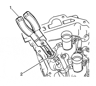
    Install the EN 46110 on-vehicle valve spring compressor above the applicable cylinder as shown.

  8. Tighten the EN 46110 on-vehicle valve spring compressor valve spring compressor nut (2).
  9. 2010-buick-enclave-valve-spring-removal

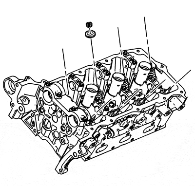
    Remove valve keepers

    Remove the valve keepers.

  10. Loosen the EN 46110 on-vehicle valve spring compressor valve spring compressor nut.
  11. Remove the valve spring retainer.
  12. 2010-buick-enclave-valve-spring

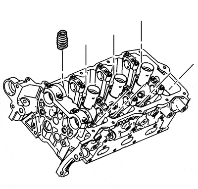
    Remove the valve springs.

  13. 2010-buick-enclave-valve-seal-removal

    Use the EN 46116 valve stem seal remover/installer  (1) in order to remove the valve stem seal (2).

Installation Procedure
  1. 2010-buick-enclave-valve-seal-removal

    Use the EN 46116 valve stem seal remover/installer  (1) in order to install the valve stem seals (2).

  2. 2010-buick-enclave-valve-spring

    Install the valve spring.

  3. Install the valve spring retainer.
  4. 2010-buick-enclave-valve-spring-removal


    Install the EN 46110 on-vehicle valve spring compressor above the applicable valve spring as shown.

    Tighten the EN 46110 on-vehicle valve spring compressor valve spring compressor nut (2).

  5. 2010-buick-enclave-valve-spring-compressor

    Install the valve spring keepers.

  6. Remove the EN 46110 on-vehicle valve spring compressor .
  7. Disconnect the J 39313 spark plug port adapter from the compressed air source.
  8. Remove the J 39313 spark plug port adapter .
  9. Install the spark plugs.
  10. Install the rocker arms and camshafts.
  11. Remove the EN 46106 flywheel holding tool .
  12. Install the starter motor.

For full instructions that include images and diagrams Select your vehicle specific Auto Repair Manual Here.