


Go Kart Braking Components
-
With the front wheels and steering components installed, the braking system can be installed. Some go-karts use band or disc brakes, some karts are stopped by means of a drum-braking system functionally similar to one used on automobiles. The braking mechanism is controlled by a lever that operates when the brake pedal is depressed.
- With the kart resting on jack stands, begin the assembly by securing the brake assembly onto the axle with bolts and locking nuts, making sure that the nylon side of the locking nuts face outward.
- Install the sprocket onto the axle with the bolts toward the frame. Make sure that the sprocket bolts are facing away from the brake.
- With the axle secured, slide the brake drum carefully over the axle and the shoe. Place the drum firmly against the kart frame, then back it off about 1/8-inch.
- Note that there is a channel cut down the length of the axle, and a corresponding notch in the drum. This allows you to install a metal key to hold the brake in place. Tap the key into the notch as far as it will go.
- Measure the portions of the axles protruding beyond the frame, and adjust them so that the overhang is identical on each side.
- Once the measurements are the same, tighten the set screws to secure the axle.
- For karts with engines of 6 horsepower or larger, disc brakes are recommended for better stopping power.
Go Kart Chain and Axles
-
With the engine, clutch and chain installed, the chain can be adjusted by making minor adjustments to the placement of the engine. If the engine is moved all the way forward, the chain will be too loose and could come off the sprocket. If it is moved all the way to the rear, it will be too tight and could break. A loose chain is a hazard, so either of these situations is to be avoided. Position the engine so that the chain has good tension, but is not overly tight.
- Once you've determined the proper positioning of the engine, secure it to the mounting plate by tightening down the lock-nuts securely on the mounting bolts using the appropriate wrenches. Locking nuts will help prevent the engine from coming loose from its mount under vibration.
Note
- A chain deflector is an important safety feature. It could prevent injury in the event that the chain ever breaks or comes loose. If the chain breaks, the deflector prevents it from flying into the kart.
- After the go-kart has had some use, the position of the engine may need to be fine-tuned later to re-adjust the chain tension.
- A split plastic-covering is used to cover the exposed portion of the axles.
- Measure the length of the exposed portion of the axle, cut sections of the axle-covering to the appropriate length, and install one on each of the four axles. The slit in the covering allows it to slide easily into place. Make certain that the axle rotates freely inside the axle guard.
- Once you've determined the proper positioning of the engine, secure it to the mounting plate by tightening down the lock-nuts securely on the mounting bolts using the appropriate wrenches. Locking nuts will help prevent the engine from coming loose from its mount under vibration.
Go Kart Installing the Engine and Clutch
Below are the general guidelines that are applicable to most go-kart assemblies. With any particular model, there may be procedures, specifications, settings, tolerances, components, etc. that are specific to that vehicle. Always consult your owner's manual when undertaking a project of this type.
In addition to standard auto-mechanic's tools, specialty tools that will be helpful for this project include an air compressor and a set of air ratchets and sockets. If you don't own air tools, you can rent them from most equipment-rental centers.
Installing the Engine and Clutch
- There were several available engine models that you can opt for. The clutch is purchased and installed separately. Installing the clutch yourself will save you money in the go-kart project.
- The engine rests on the engine mounting plate (figure A), and is bolted in position through four slotted mounting holes in the plate. The holes are slotted so that the engine position can be shifted forward or backward to adjust the tension on the chain, which will be installed in a later step.
- Secure the engine to the mount using the provided mounting bolts and nylon lock-nuts. The bolts extend up through the bottom of the plate and engine. When installing the nuts, make certain that the nylon side of the nut is facing away from the threads of the bolt (figure B). Install all four bolts and nuts, but don't tighten the nuts down yet. The engine will need to slide forward and backward for chain adjustment.
- The next step is to install the clutch. Note that the clutch assembly has a front and back that are not interchangeable. The front side (figure C) has clutch-sprockets while the back (figure D) has key that installs in slot and holds the clutch in position on the engine Two set-screws help secure the clutch to the crankshaft.
- Align the key on the clutch with the key-way on the crankshaft, and make sure that the clutch is seated firmly against the crankshaft plate (figure E).
- Fasten the clutch using the provided bolt and flat-washer (figure F).
- Tighten the bolt securely using the appropriate socket.
- It's a good idea to oil the clutch after each use.
Installing the Chain
- The chain installs on the sprocket and comes already cut to length. It is formed into a complete loop using a master link.
- Place the chain on the lower sprocket, and bring the end up over the clutch sprocket.
- Where the two ends of the chain, the ends are fastened using a master link which is secured using a tiny link-washer and link-clip.
- Fasten the two ends together at the master link, install the washer, and the clip. Use needle-nose pliers to make sure that the clips snaps completely into place to secure the master link.
- This competes the installation of the chain. If the chain ever needs to be removed from the kart, the clip can be removed so that the two ends can be disconnected.
- With the chain installed, check to make certain that the top and bottom sprockets are aligned with each other.
- Once the sprockets line up, and the chain is straight up-and-down, mark the location of the lower sprocket on the axle, then install the key provided to secure the lower sprocket to the axle shaft. Use a hammer and pin to tap the key in as far as it will go.
Go Kart Installation of Rear Wheels and Pedals
- The rear tires install onto the wheels in the same manner as they did on the front. The rear wheels do have a different arrangement with respect to the bearings. On the rear, the bearing-hub assembly is mounted onto the frame. The wheel attaches to the assembly by means of a key-way in the center of the wheel.
- Line the key-way on the wheel up to the corresponding channel on the axle. With the wheel in place, slide the key into the channel in the axle, and tap the key into the wheel.
- Use a nylon locking nut to secure the wheel assembly to the axle, using the appropriate sized socket.
- Repeat the steps on the other side to install the other rear wheel.
- With all of the wheels installed, the gas and brake pedals can be installed. There are separate left and right pedals, and they are different. Make certain you install them properly. The foot-pedal on each should be oriented to the inside of the frame.
- First, install the brake pedal on the left side of the kart using a lock washer and nylon lock-nut.
- Install the gas pedal on the right side of the kart using the same technique.
- Tighten down the bolts for each pedal, but avoid over-tightening the nuts. Over-tightening will cause the pedals to feel stiff during operation.
- With both pedals in place, the brake control rod can be installed. The end of the rod is 90-degree bend, and inserts into one of the holes in the shaft of the brake pedal (figure G). For this particular kart, the rod is inserted into the second hole.
- Since the rod extends toward the back of the kart to the rear brake, and underneath the steering hoop, it may need to be bent slightly to clear the hoop.
- Use a retaining clip to secure the rod to the pedal.
- At the rear of the kart, the rod attaches to the brake lever by means of a clevis. This is the location where brake adjustments can be made, if necessary.
- With the clevis installed on the end of the rod, line the hole in the clevis up with the corresponding hole in the lever.
- Insert the clevis pin through the holes to secure the rod.
- With the brake pedal and rod attached, applying pressure to the brake pedal should cause the brake mechanism to engage. Make the final adjustment by tightening the brake lever where it hooks to the backing plate.
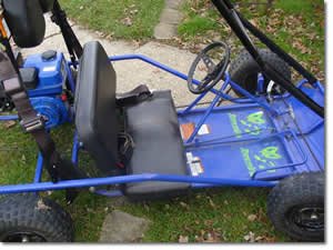
Go Kart Seat Installation and Completion
The final major installation on the go-kart is the seat. A final safety feature is a kill switch which allows the driver to instantly shut off the engine in the event of an emergency.
- The seat is fastened to the kart chassis using two metal brackets. The shorter bracket goes toward the front of the kart, since the frame narrows toward the front.
- Position the brackets to the bottom of the plastic, molded seat, and attach it with the lag-bolts provided in the kit.
- Tighten the bolts down securely using the appropriate socket. Avoid over-tightening as this could crack the plastic seat.
- Once the brackets are attached, position the seat on the kart chassis. Make sure the assembly is seated firmly on the frame.
- The brackets fit over the frame and are secured with bolts, washers and locking washers. There are a total of four bolts used to secure the seat to the frame. For extra security, locking nuts are used to fasten the bolts.
- Once the plastic seat is in place, install the vinyl slip-cover. It tucks easily around the seat.
- The last installation needed to complete the kart is the driver's emergency kill-switch. This allows the driver to instantly shut off the kart's engine in the event of an emergency.
- The kill switch mounts on the kart's frame rail, right next to the driver's seat. The wiring is run to the back of the kart, taking care to avoid tangling it in the rods and linkage. The wiring is secured with zip-ties.
- The switch is electronically tied in to the kart's on/off switch.
- Locate the black wire on the on/off switch. The black wire supplies power to the ignition system on the engine.
- Tap into the black wire, and secure the kill-switch connection using a plastic scotch lock. An alternative is to simply strip and splice the two wires, but the scotch lock is simpler, and will hold the wires securely.
- Re-install any components that were removed earlier when installing the engine.
- Check the final adjustments on the brake and throttle, and install the cotter pin into the clevis pin on the throttle.
- You can adjust the throttle to your liking using the spring and nut on the throttle rod.
- With the kill-switch installed, and final adjustments made, the kart is ready for use. Check the oil, tire inflation, and make sure the kart has gas before starting. Depending on your model, there may be other items on the final checklist. Check your manual.
Go Kart Throttle Assembly
The throttle is a two-part assembly, including the rod and the cable. Install the rod first.
- Position the rod on the right side of the kart so that the straight, threaded end can be inserted through the first frame bracket.With the threaded end in place connect the other end which has a 90-degree bend at the end through the second hole in the pedal gas-pedal assembly, and secure it with the provided retaining-clip. Make certain that the concave side of the clip faces the brake pedal. The clip ensures that the rod cannot come loose from the pedal.
- At the straight, threaded end of the rod, install the spring so that the larger diameter of the spring is facing toward the front frame bracket.
- Once the spring is in place on the rod, install the retaining nut on the threaded end. Adjusting the location of the nut on the threaded rod will provide the ability to adjust the spring tension for precise throttle control.
- With the spring and nut installed, check the operation of the assembly by pressing on the gas pedal.
Note:
- Once the kart is operational, inspect the spring and nut regularly.
- The second main component of the throttle assembly is the cable. On one end is the bare cable, and at the other end is a cable-pull.
- Place the end with the cable-pull into the clip on the side of the engine, and insert it until the metal sleeve on the cable is secured by the clip. The metal sleeve prevents the cable from being crimped by the clip.
- Use needle-nose pliers to secure the cable-pull into the linkage on the side of the carburetor.
- With the end of the cable in place, tighten the clip using a phillips screwdriver.
- Because the cable provided with this kit is longer than necessary, the overall length of the cable is shortened by looping the cable twice, and securing the looped portion to the kart's frame using plastic zip-ties. Three ties should be sufficient to secure the cable. Tighten the ties, and snip off the excess.
- To finish installing the cable, install the plastic bushing provided into the rear frame-bracket hole, and install the cable through the bushing. The plastic bushing prevents the cable from chafing against the metal.
- Use needle-nose pliers to bend the end of the bare cable 90 degrees, and insert it into the hole at the threaded end of the rod.
- Install the cable-lock that secures the cable to the rod.